


The Honda BF50 Wiring Diagram You’ll Ever Need: A Comprehensive Guide
Owning a Honda BF50 outboard motor is a fantastic way to experience the joys of boating. Whether you’re a seasoned sailor or a weekend warrior, knowing your motor’s electrical system is crucial for maintenance, troubleshooting, and ensuring a smooth ride. This article serves as your comprehensive guide to the Honda BF50 wiring diagram, providing you with the information you need to understand and effectively utilize this vital resource. We’ll break down the key components, offer helpful tips, and address frequently asked questions, ensuring you have the knowledge to keep your BF50 running reliably.
Understanding the Importance of a Wiring Diagram
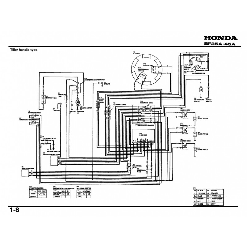
A Honda BF50 wiring diagram is essentially a visual blueprint of your motor’s electrical system. It illustrates how the various components – such as the battery, starter motor, ignition system, charging system, and various sensors – are interconnected. This diagram is invaluable for several reasons:
- Troubleshooting Electrical Issues: When your BF50 experiences electrical problems (e.g., no starting, intermittent running, charging issues), the wiring diagram helps you pinpoint the source of the problem.
- Component Replacement: If a component fails, the diagram helps you identify the correct wires and connectors for proper replacement.
- System Modifications: If you plan to add accessories (e.g., gauges, lights), the diagram helps you understand how to integrate them safely and effectively.
- Preventative Maintenance: Understanding the wiring diagram allows you to inspect connections, check for corrosion, and perform preventative maintenance to avoid future problems.
Key Components and Their Wiring in the BF50
The Honda BF50’s electrical system, like any modern outboard, is complex. Understanding the major components and their wiring is key. Here’s a breakdown:
- Battery and Starting Circuit: This circuit powers the starter motor, which cranks the engine. Key components include:
- Battery: Provides the initial electrical power.
- Starter Motor: Engages the flywheel to start the engine.
- Starter Relay/Solenoid: Controls the flow of high current to the starter motor.
- Ignition Switch: Activates the starting circuit.
- Fuses and Circuit Breakers: Protect the system from overcurrent.
- Charging System: This system recharges the battery while the engine is running. Key components include:
- Alternator/Stator: Generates AC electricity.
- Rectifier/Regulator: Converts AC to DC and regulates voltage.
- Wiring: Connects the alternator to the rectifier/regulator and then to the battery.
- Ignition System: This system provides the spark to ignite the fuel-air mixture in the cylinders. Key components include:
- Ignition Coil: Produces the high voltage needed for the spark plugs.
- Spark Plugs: Generate the spark.
- CDI Unit (Capacitive Discharge Ignition): Controls the timing of the spark.
- Trigger/Pick-up Coil: Signals the CDI unit when to fire the spark plugs.
- Sensors and Control Modules: These components monitor engine parameters and control various functions. These can include:
- Temperature Sensors
- Oil Pressure Sensors
- Throttle Position Sensor (if equipped)
- ECU (Engine Control Unit) - on some models
How to Locate and Interpret the Honda BF50 Wiring Diagram
- Obtaining the Diagram:
- Service Manual: The most reliable source is the official Honda BF50 service manual. These manuals provide detailed wiring diagrams specific to your motor’s model year.
- Online Resources: You can often find wiring diagrams online, especially on boating forums or through aftermarket parts suppliers. Be sure to verify the diagram’s accuracy and compatibility with your specific motor.
- Interpreting the Diagram: Wiring diagrams use standardized symbols to represent components and wiring connections.
- Wires: Wires are typically color-coded to indicate their function. Common colors include:
- Red: Positive (+) power
- Black: Negative (-) ground
- Yellow: Charging system
- Blue: Ignition
- Connectors: The diagram shows where wires connect to each other and to various components.
- Fuses and Circuit Breakers: These are represented with specific symbols.
- Wires: Wires are typically color-coded to indicate their function. Common colors include:
Troubleshooting Tips Using the Wiring Diagram
- Identify the Problem: Begin by describing the symptom (e.g., “won’t start,” “no spark,” “charging issue”).
- Consult the Diagram: Locate the relevant circuit in the wiring diagram.
- Check for Power: Use a multimeter to check for voltage at key points in the circuit.
- Inspect Connections: Examine connectors for corrosion, loose connections, or broken wires.
- Component Testing: Use a multimeter to test the resistance or continuity of components like coils, sensors, and switches.
- Follow the Circuit: Trace the wires from the power source to the affected component, looking for breaks or shorts.
Safety Precautions When Working with Electrical Systems
- Disconnect the Battery: Always disconnect the negative (-) battery terminal before working on any electrical component.
- Use Proper Tools: Use insulated tools to prevent electrical shock.
- Work in a Well-Lit Area: Ensure you have adequate lighting to see the wiring and connections clearly.
- Double-Check Your Work: Verify all connections and ensure wires are routed correctly before reconnecting the battery.
- Seek Professional Help: If you are not comfortable working with electrical systems, consult a qualified marine mechanic.
Frequently Asked Questions (FAQs)
1. Where can I find the specific wiring diagram for my Honda BF50?
The most reliable source is the official Honda BF50 service manual for your motor’s specific year and model. You can often find these manuals online or at marine parts retailers.
2. What do the wire colors mean in the Honda BF50 wiring diagram?
Wire colors are typically standardized. Red is usually positive (+), black is ground (-), yellow is associated with the charging system, and blue is often for the ignition system. However, always consult the diagram for your specific model.
3. How do I test a component with a multimeter?
Use the multimeter to check for voltage, resistance, or continuity, depending on the component. Consult the service manual for the specific test procedures and expected values for each component.
4. My BF50 won’t start. Where should I start troubleshooting using the wiring diagram?
Begin by checking the starting circuit. Look at the wiring for the battery, starter motor, starter relay/solenoid, and ignition switch. Check for voltage at the battery terminals, then at the starter relay, and finally at the starter motor itself when the key is turned.
5. What if I’m not comfortable working on the electrical system myself?
It’s always best to err on the side of caution. If you’re not comfortable working with electrical systems, consult a qualified marine mechanic. They have the expertise and tools to diagnose and repair electrical problems safely and effectively.
Conclusion
The Honda BF50 wiring diagram is an indispensable tool for any owner. By understanding the components, interpreting the diagram, and practicing safe troubleshooting techniques, you can confidently maintain and repair your motor’s electrical system. This comprehensive guide provides the foundation you need to navigate the complexities of the BF50’s wiring and keep you enjoying your time on the water. Remember to always prioritize safety and seek professional help when needed. Happy boating!
