


Decoding the Maze: A Step-by-Step Guide to Reading Piping and Instrumentation Diagrams (P&IDs) for Beginners
Piping and Instrumentation Diagrams (P&IDs) are the blueprints of the process world. They’re intricate visual representations of piping systems, instrumentation, and equipment used in industrial plants, chemical facilities, and various other complex systems. For beginners, these diagrams can seem overwhelming – a chaotic jumble of lines, symbols, and cryptic notations. But fear not! This comprehensive guide will break down the process of reading a P&ID step-by-step, transforming you from a bewildered observer into a confident interpreter.
This article is designed to equip you with the fundamental knowledge and skills necessary to navigate these essential diagrams. We’ll cover the key elements, symbols, and strategies for understanding the flow of information and equipment within a process system. Let’s dive in!
1. Understanding the Purpose and Scope of a P&ID
Before you even look at a P&ID, it’s crucial to understand its purpose. A P&ID serves as a detailed schematic of a process, providing:
- Process Flow: Visualizing the flow of fluids, gases, and other materials through the system.
- Equipment Representation: Identifying and depicting all major equipment like vessels, pumps, heat exchangers, and instruments.
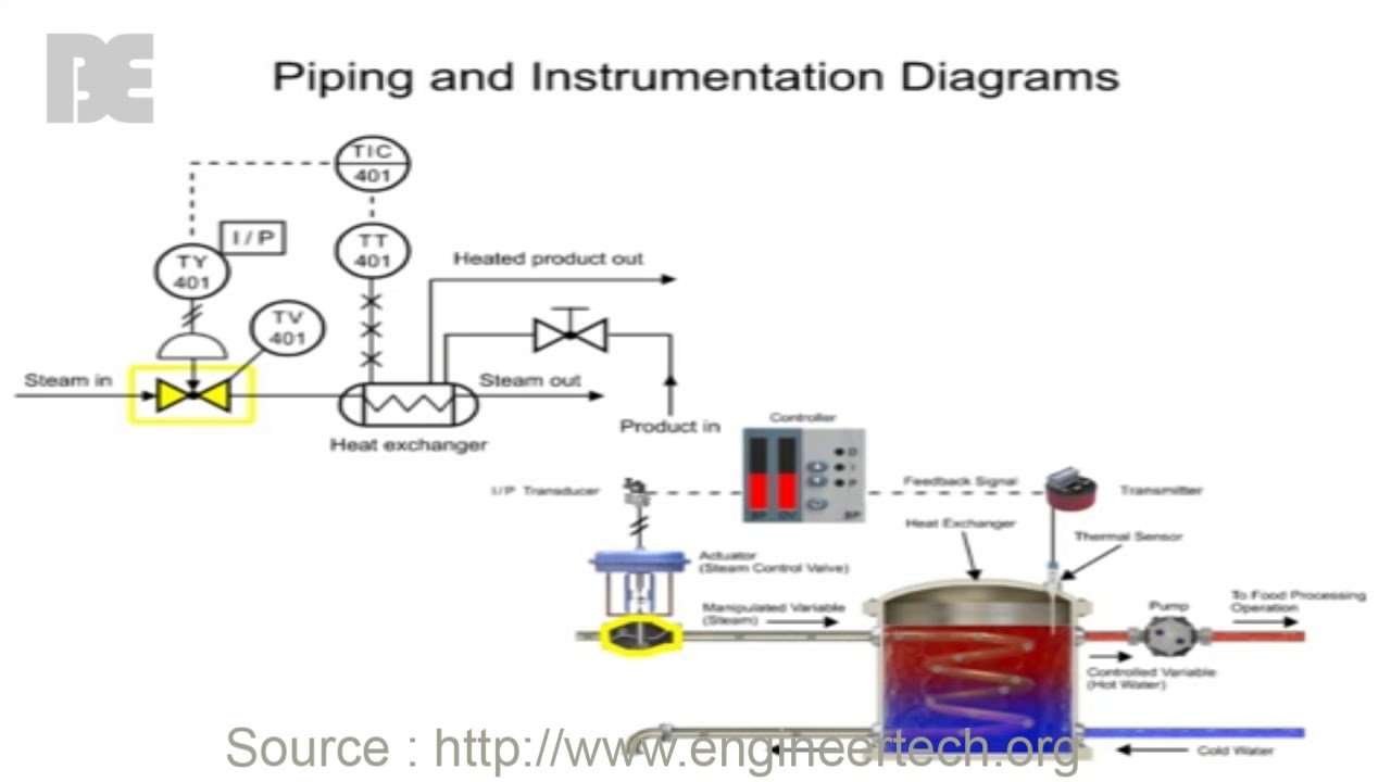
- Instrumentation: Showing the location and function of instruments used for measuring, controlling, and monitoring process variables (e.g., temperature, pressure, flow).
- Piping Information: Detailing the size, material, and connections of pipes that carry the process fluids.
- Control Systems: Illustrating how the process is controlled and automated.
- Safety Information: Highlighting safety devices and systems.
Essentially, a P&ID acts as a single source of truth for understanding the entire process, used by engineers, operators, maintenance personnel, and other stakeholders.
2. Familiarizing Yourself with Common P&ID Symbols and Components
The language of P&IDs is visual. Learning the common symbols is the first step to unlocking their secrets. Some key elements to recognize include:
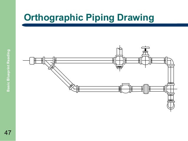
- Piping: Represented by lines. Different line types indicate different aspects:
- Solid Lines: Main process piping.
- Dashed Lines: Control signals or utility lines.
- Dotted Lines: Instrument signal lines.
- Numbering System: Piping is typically labeled with a number, size, and material specification.
- Equipment: Drawn with standardized symbols:
- Vessels: Cylinders, spheres, or other shapes indicating tanks, reactors, or separators.
- Pumps: Circles or rectangles with specific symbols.
- Heat Exchangers: Rectangular boxes with internal details representing heat transfer surfaces.
- Valves: Various symbols representing different valve types (gate, globe, ball, check, etc.).
- Instrumentation: Identified by circles with tags:
- Instrument Tag: Contains a letter code and a number to identify the instrument (e.g., TI-101 - Temperature Indicator 101).
- Letters: Standardized letters indicate the measured variable (e.g., T for Temperature, P for Pressure, F for Flow).
- Lines: Indicate how the instrument is connected to the process (solid, dashed, dotted).
- Line Numbers: Each pipe segment is assigned a unique line number. This number provides information about the pipe size, material, insulation, and process fluid.
Tip: Invest time in studying a comprehensive P&ID symbol legend. Most diagrams include a legend that explains the specific symbols used within that document.
3. Breaking Down the Diagram: A Step-by-Step Approach
Reading a P&ID can be systematically approached:
- Start with the Title Block: This area contains crucial information, including:
- Project Name and Number
- Diagram Title
- Sheet Number
- Revision History
- Company Information
- Identify the Process Boundaries: Determine the scope of the diagram. Where does the process begin and end? Look for inlet and outlet streams.
- Trace the Flow: Follow the piping lines from the inlet to the outlet, noting the direction of flow using arrows.
- Identify Equipment: Locate and identify major equipment, such as pumps, vessels, and heat exchangers. Understand the function of each piece of equipment.
- Analyze Instrumentation: Examine the instrumentation associated with each piece of equipment and process line.
- What is being measured (e.g., temperature, pressure, flow)?
- How is it being measured (e.g., transmitter, indicator, controller)?
- What actions are being taken based on the measurement (e.g., control valve adjustment, alarm)?
- Understand Control Loops: Follow the control lines (dashed or dotted) to understand how the process is controlled. Identify the controller, the measurement, and the control element (e.g., control valve).
- Note Valve Types and Positions: Pay attention to the type and position of valves as these control the flow of the process.
- Use Line Numbers: Refer to the line numbers to obtain detailed information about the piping specifications.
- Cross-Reference Information: Use the diagram’s symbols and tags to cross-reference information in other documents (e.g., equipment datasheets, instrument lists).
4. Practical Tips and Best Practices
- Start Simple: Begin with simpler diagrams and gradually move towards more complex ones.
- Practice Makes Perfect: The more you practice reading P&IDs, the easier they will become.
- Use a Highlighter: Highlight key elements like equipment, instrumentation, and control loops to track them.
- Ask Questions: Don’t hesitate to ask experienced colleagues or supervisors for clarification.
- Utilize Software: Many software programs are available to view and interpret P&IDs, offering features like interactive navigation and symbol definitions.
- Review the Legend: Always refer to the legend to understand the specific symbols used in the diagram.
- Focus on the Process: Always keep the overall process in mind to understand how each component contributes to the system’s function.
Conclusion: Mastering the Language of the Process
Reading P&IDs is a fundamental skill for anyone working in the process industries. By understanding the purpose of these diagrams, familiarizing yourself with the symbols, and following a systematic approach, you can unlock their valuable information. This guide has provided a solid foundation for beginners. With consistent practice and a willingness to learn, you’ll soon be able to decode the complexities of P&IDs and contribute effectively to process design, operation, and maintenance.
FAQs
1. What is the difference between a P&ID and a PFD (Process Flow Diagram)?
A PFD (Process Flow Diagram) is a simplified diagram that shows the basic process flow, equipment, and major process streams. A P&ID is a much more detailed diagram that includes all equipment, instrumentation, piping, and control loops. PFDs are used for process design and conceptual understanding, while P&IDs are used for detailed engineering, construction, and operation.
2. Where can I find P&IDs?
P&IDs are typically maintained by the owner/operator of a facility and are used by all the stakeholders. They’re often stored in a document management system and can be requested by authorized personnel involved in the project or facility. They are also provided by engineering firms during the design and construction phases of a project.
3. How do I interpret instrument tag numbers?
Instrument tag numbers follow a standardized format. The first letter typically indicates the measured variable (e.g., T for Temperature, P for Pressure, F for Flow). The second letter indicates the function of the instrument (e.g., I for Indicator, C for Controller, T for Transmitter). The number at the end is a sequential number for instruments of the same type. For example, TI-101 is a Temperature Indicator number 101.
4. What are the common units used in P&IDs?
The units used in P&IDs depend on the industry and location. Common units include:
- Temperature: Celsius (°C) or Fahrenheit (°F)
- Pressure: Pascals (Pa), Bar, pounds per square inch (psi)
- Flow: Cubic meters per hour (m³/h), liters per minute (L/min), gallons per minute (gpm)
- Level: Meters (m), feet (ft)
5. What if I find an error on a P&ID?
If you find a discrepancy or error on a P&ID, it is important to immediately report it to the appropriate personnel, such as an engineer or supervisor. Errors can lead to misinterpretations and potentially hazardous situations. Often, a formal procedure for reporting and correcting P&ID errors is in place.
